|
Saw a Retweet by @moogmusicinc of a tweet
regan p. akers @Reganomics92
Moog Accordion. Have you thought about it? and it inspired me to start to make a Midi Accordian. 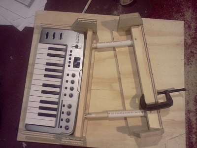
Using bits of pipe and dowel left over from my Cello project, I made two pivoting sliders and use some chain to stop the two halves from moving too far apart. I took an old game controller apart and used one of the joysticks to sense the movement between the two halves. 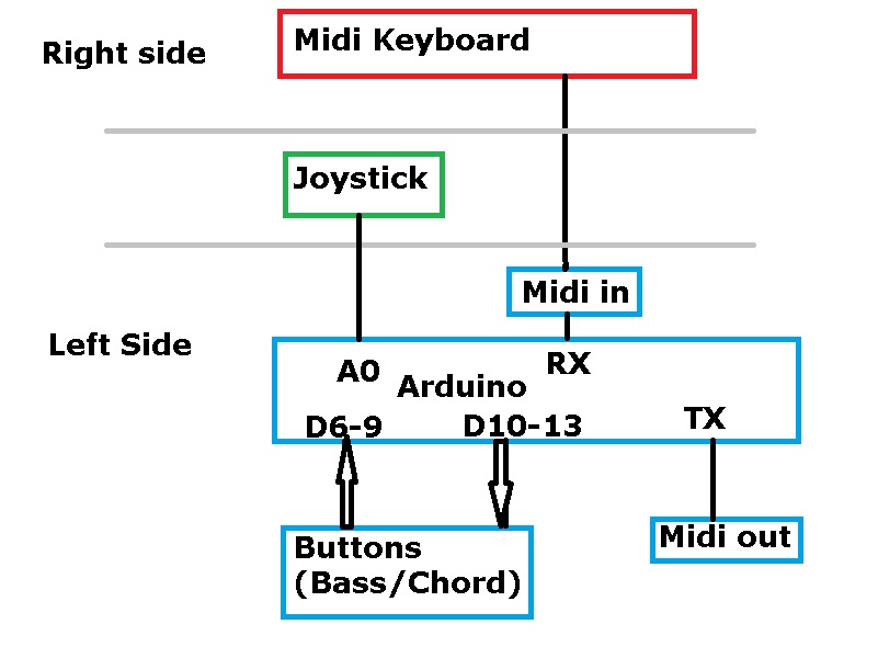
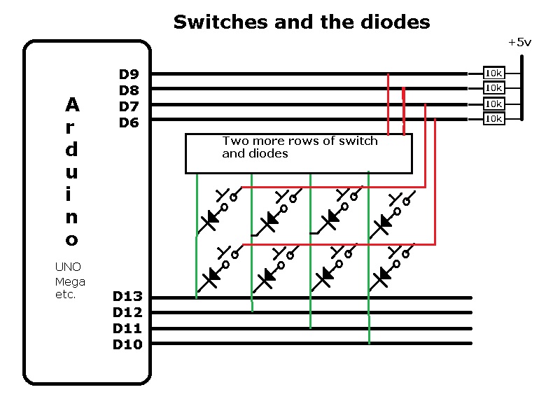
The Arduino controller is connected to a joystick on the analog input A0. A midi optoisolator circuit converts the midi current-loop interface to logic levels and goes to the RX input on the Arduino. The TX output is connected to the 5 pin DIN midi output socket using two 100 ohm current limiting resistors. Four digital outputs (D10-13) are used to drive a matrix of switches. Four digital inputs (D6-9) are used to read the 'row' values.
The software that runs on the Arduino uses pieces of software from my previous projects such as
midi guitar, the Aniversal midi controller
and the Doodlebug midi to keyboard convertor that can be used to play the Google Doodles.
|
  |